GPS project: field test

in the wild

I got a chance to field test the GPS unit yesterday. Overall I’m quite happy with how things went. Even though it’s quite large for a GPS unit, the box fits nicely into my small pack, and everything functioned fairly well during the hike.

I can already see that the buttons need to be recessed somehow. I opened my pack a couple of times to check on things, and the backlight was on each time. This means that the buttons are being hit as the unit moves around in my pack. On a short hike this was ok, but on a long one it would drain the battery much faster.

One thing that I wasn’t prepared for is the fact that my phone is very hard to see clearly in direct sunlight (which we were in during the entire hike!), and impossible to photograph under any conditions (it’s like a mirror).

Even with those problems, Google Maps was very accurate with the GPS data that the unit was feeding it, and since I had a cell signal I had satellite imagery during the hike. The GPS data from the hike is pretty good, although I am going to have to use some averaging or filtering to clean the data up a bit. I have a map with the raw data here, and you can see that when we take a break the data points tend to “wander around”. I think that it’s time to get to know GPSBabel.

0 Comments

GPS project: box it up

Now that the hardware side is pretty much wrapped up I wanted to build a simple enclosure so that I could start field testing. I’ve already spent way too much time trying to find a prebuilt enclosure that would fit the components nicely. As I get further along with my projects I’ll write more about enclosures.

Inspired by the design of the Digg Button and Wave Bubble, I decided to do a simple sandwich of acrylic sheets and spacers. I couldn’t sandwich the boards directly like was done in those projects, so I decided to mount my boards to the back and face of the enclosure. With this basic design in mind, and some notes on what size screws each board could take, I set off for the hardware store.

tapcut pipe 
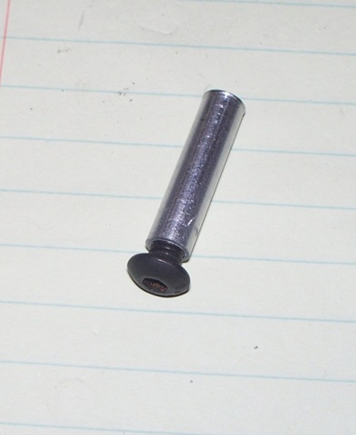
For the mounts I used 1/4” x 030 (6.35 mm) aluminum rod. I chose this size since it’s just small enough to be tapped for a 10-32 screw.

While SAE and metric sizes are not interchangeable, a M5 x .08 is pretty close to this.


tappedI cut the rod to length with a twist pipe cutter and then tapped both ends with a 10-32 tap.

Tapping the aluminum is pretty easy going, just make sure to use a little oil to keep the tap moving smoothly, and back up every few turns to keep the cut smooth.screw


I cut and tested a small piece of the rod before moving on to the full length pieces.


done Once I was happy with the test piece I measured, cut, and tapped the 4 corner pieces.

I Used a paper towel between the rod and the pliers to keep from marring the aluminum while tapping them.

Even after measuring and cutting carefully there was still a small difference in the length of each piece. I used a sander to bring them all to the same height, and chased the threads with the tap again.


macroline

I found rubber grommets to use as standoffs for the Arduino and Lithium Backpack boards, but couldn’t find any small enough to use for the Bluetooth board. For these I used short sections of macroline that I had in my paintball gear box.

Macroline is 1/4” nylon tubing that cuts easily with a razor blade. I had a bit of trouble getting it to cut straight at such short lengths, so I used the pipe cutter to score a deep ridge (the pipe cutter can’t cut the line since it is too soft). Then I used the ridge as a guide to cut the line by rolling it on the desk while pressing the razor blade into it.

drilled readyI cut the Lexan (polycarbonate) sheet that I got at Lowes, and rounded the corners.

I just happened to have a small corner rounder from a prior business venture, but you could achieve the same effect with a band saw, or sander.

Once I had cut the top and bottom sheets, I taped both together and marked and drilled the outside corner holes. I also marked the holes for the Arduino and the Lithium Backpack while I was laying everything out.


bottom mounted

Next I mounted the corners and the boards to the polycarbonate sheet. The boards are mounted with 4-40 screws (again, not exact but M3 x .05 is pretty close). I had purchased nylon washers in case the nuts were too close to a traces or component on the boards, but it turned out that I didn’t need them.


front

I then repeated the steps with the front. The LCD is mounted with 4-40 screws, as is the Bluetooth.

The Bluetooth only has 3 screws right now, since the hardware store only had 9 of that size in stock, and I used 6 to mount the boards. For now it does the job just fine.

The switch is mounted with 2-56 screws (approximately 2.1 mm).

Once I had the face done, I started routing wires to get everything hooked up, and bolted both halves together.


Below are a few shots of the completed enclosure.

assembled assembled 2


glamor shot1

glamor shot 3


Final thoughts:

Overall I’m happy with the results of the enclosure as a general purpose concept. For the GPS unit it’s a bit large, and not horribly strong, but I knew that this was going to be an issue going in. From the hardware standpoint I have learned quite a bit;

  • Connectors and wires take up a lot of space.
  • Extra boards take up a lot of space.
  • The area taken up by mounting screws adds quite a bit of size to the enclosure.
  • I don’t care for the membrane buttons. I prefer the tactile switches, but that’s me.

For now I’m done with the hardware side of this project, but I have quite a bit more software work to do. Once I get the software completed and field tested (and probably another project done), I’ll focus on reducing the overall size of the components, and then finding or making another enclosure for it.

2 Comments

GPS project: hardware complete!

complete

After two evenings (late into the night) of soldering and de-soldering and re-soldering,  I have the hardware side of the project pretty much complete.
Here’s the entire setup; in this shot I had everything pushed in tightly to get an idea of the final size. You can see the electrical tape on the back of some of the boards to prevent shorts.


switchboardInstead of tactile switches, I chose to use a silicone button that resembles a TV remote. Here the PCB half of the buttons is mounted on a 1" (2.5 cm) square ProtoBoard along with a header that provides power, ground, and a return to the two button pins. I built the pull down resistor circuits on the board under the button PCB.


lcdboard

Two more of the little boards make up the breakout board for the LCD. I thought that I had ordered a larger board to build this on, but must have missed it. Luckily I had ordered a few extra of these just to have around. They are nice little boards; each group of 3 holes has a trace between them. Wiring up small breakouts like this is a breeze since everything is through hole, and there are no other connections on the back.

lcdmounted

The trim pot for the LCD contrast is on this board as well. This is one part of the design that will probably change at some point. It is a pain to adjust since it is behind the LCD. Depending upon how easy it is to see the LCD outside, I may even have to put a full size pot (or a linear one) somewhere.


new headers I removed the original headers from the GPS Logger Shield, and replaced them with polarized connectors. I figured that this would make maintenance and hookup easier. Ultimately I would like to have projects that are contained on shields or custom boards, but since I’m not sure what the end result of finding or building an enclosure will be, I decide to go with connectors for this one.


power

Since the unit can be powered from USB or battery, and since the battery will charge when the Arduino is plugged in, I built a small power distribution board to make sure that everything that needed power got it.

The Arduino’s 5v and ground are running to the LCD which in turn is forwarded to the power board. The battery plugs directly into the power board, and then feeds the Bluetooth and buttons.


Below are a few shots of the various cable runs. I really should get some more wire, in different colors, but they only had 3 colors at Sparkfun!

lcdboardhu

Connectors to the LCD, and power board.

hookedup

Everything plugged in up top. Notice the new jumper for the GPS. I didn’t want to hard wire anything at this point. The white wires running to the right go to the buttons and Bluetooth.

newharness

Everything hooked up!

At this point there is still one more wire to hook up: I forgot to do the battery monitor wire.

I still have some software issues to tackle, but I think I’m going to get it bolted to something first. I’m planning to take the entire unit for a short hike on Saturday, so I’ll get to test it out.

0 Comments

GPS project: caught up?

The last post brings us up to speed on this project. I have quite a bit more work to do over the next few weeks to get it finished up:

  • I need to finish up the hardware side of the project: This will happen over the next few days, as I have a large order of small parts coming from Sparkfun today!
  • I have to get the rest of the menu options worked out, and functioning.
  • I have to extend some of the functions from the underlying SD card library out to the sketch, so that I can delete files from the Arduino, open and read files, etc.
  • I want to write a helper app for the PC side. It will need to be able to send a few commands via serial, and then stream the file data back to the PC side, parsing the NMEA sentences, and splitting out the way points that I have added via the button menu. Writing the app will simple, but I would like to get it working on mono, so that it is usable on multiple platforms.
  • I would like to make the way points based on some standard system so that they can be easily imported into Google Earth, or other geo aware apps.
  • I want an enclosure! This has been a particularly frustrating part of this project, and one that I’m quite positive I’ll have some lengthy posts on in the near future.
0 Comments

GPS project: more gps data

Another task on my “to do” list was to work out the various settings that could be enabled on the GPS receiver itself. After a bit of research I decided that I was only interested in the RMC and GGA outputs.

I was already getting the RMC data which gave me latitude, longitude, ground speed, track angle, date, and time. By adding the GGA sentence I would also get altitude, the number of satellites that the unit was using, and a couple of reference values for the quality of the data.

I enabled the GGA output, and went to work getting the parsing routines capable of managing two different sentences. Overall this should have been a rather simple task, but while I was splitting the code up into sub routines a couple of weeks ago, I misplaced a variable that managed the position in the parsing buffer. This caused no issues when only one type of sentence was being output from the GPS. Once the GPS started sending two sentences back to back, the result was not so pretty. Basically I lost half of a Sunday trying to debug this. Once I found the missing “return”, it was a quick task to get the new variables parsed out for the LCD.

I revisited the menu function, and added the appropriate handlers so that I could use button two to toggle between the a screen with location data, and one with direction, altitude, ground speed, and satellite count.

0 Comments

GPS project: batteries and buttons

100_1556

The Lithium Backpack from Liquidware is a pretty straight forward affair. It has outputs for +3.3, +5, and ground, along with a status pin. I added three more wires to the “shield” that I created for the LCD. This brought the +5 and ground pins from the backpack, to the corresponding pins on the Arduino, and connected the status pin to an analog pin. At this point I could add the % of battery left to the LCD, but left the work of getting accurate data for later on, and just used the analog value, since I had some data flowing, and wanted to work on the menu system.

The only issue with the backpack (that probably only pertains to the extended model with its’ tall battery) is that the pins on the reset button were pressing against the top of the battery, and tore into its’ protective cover within a couple of days. A third standoff in the kit would solve the problem. I submitted this suggestion on the liquidware site, and got a prompt response, so here’s hoping that they’ll add another one for future orders.

On to buttons:

I wired up two buttons on the breadboard, and stole two pins from the GPS Logger shield (since I had the LCD menu, I had removed the code that used LEDs to display fix and SD card write status, so these pins were free).

I worked through a couple of different libraries, and samples for switch code, before deciding to use Jeff Saltzman’s press and hold sample code.

In order to conserve battery life, I implemented a routine to turn the backlight on the LCD off after 30 seconds. On the first button press (either button) the app checks for the backlight, if not on, then it turns it on and ignores the rest of the button check routine.

The menu system is based on two buttons controlling 4 menus.A single press of button 1 engages a “tagging” menu. Once this menu is engaged, button two is used to scroll down through the list of options (in a loop). Pressing button 1 again writes the selected tag (waypoint) to the file on the SD card. Pressing and holding button one brings up a “mode” selection menu. Again button two is used to cycle through the menu options, and pressing button one again exits the menu, applying the selected mode. Modes will be used to turn features on and off to save power when not using a feature. Button two is used to toggle between longitude / latitude display, and advanced information display screens. The press and hold on button two will have an additional menu added to it, but I’m not sure what at this point.

Next I’ll outline extending the output from the GPS (and parsing / displaying the data), and getting the battery monitor code cleaned up.

0 Comments

GPS project: the Bluetooth saga

BluetoothSo my shiny new replacement Bluetooth module was in, including a return shipping label for the bad one! I hooked it up, and after a few minutes realized that it had the same symptoms as the “bad” one laying on my desk.

After some testing, including multiple reboots, installing putty, and a quickly thrown together .NET serial port listener, I finally had a single instance of success, where I attached to the port with putty, and low and behold there were ASCII strings streaming across the screen. I went back to the Arduino IDE, and the connection was gone. I began seeing a pattern, and after fiddling with it for a while, got a reproducible set of steps. The port was locking open after the Arduino IDE had been started (and in fact wasn’t showing as an available port in the IDE), and the only way to get the port available again (to other apps) was to cycle the power to the Bluetooth device. At this point I plugged the “bad” module back in, and attached to it with putty. Of course it worked just fine.

I sent a quick note to Tom at Hacktronics to let him know my findings, and even offered to pay for the shipping since the device wasn’t bad. He politely declined my offer. Once again: Way to go Hacktronics! I wish they had a larger selection of parts, so I could give them more of my business.

At this point I had a working device, but still a couple of issues. I couldn’t use / listen to it via the Arduino IDE, and in fact once the IDE had been started, I would have to cycle power on the device to make it work. On top of that, the IDE had become very slow and sluggish since adding the Bluetooth serial ports to my machine. A bit of research on the “sluggish” issue revealed that it was a known problem in a serial library used in the IDE, and in fact there was a user fixed version of the library available. My particular issue was not part of the documented problem or fix, but I figured it would be a good starting point. Once installed, all of the problems with the device cleared up.

Now I could get back to the task at hand, which happened to be adding 3 lines of code: declaration of an instance of NewSoftSerial, calling the instance constructor with a baud rate, and a single call to pass the char from the hardware serial port to the software serial port before passing the data further into the app for processing. I spent the rest of the evening getting the info flowing into Google Maps on my HTC Touch Pro.

Now I could turn my attention back to the software side of the project. My next task was to add some buttons, and get menus built, but before I jumped into all that I wanted to get some cleanup done. I spent a couple of evenings breaking the loop into individual routines to handle different tasks, removing orphaned routines and variables, and other general housekeeping.

Next I’ll outline the Lithium Backpack setup, and adding buttons and menus that take the project from a simple logger, to a limited feature GPS device.

0 Comments

GPS project: show me something

no-fixOne of the great things about Arduino is the maturity of the product, and the user base that has grown up around it. I have found that there aren’t many problems that others haven’t already solved, and there is a large base of libraries available to do many of the chores that need to be done in an average project.

With a simple “#include”, 7 or 8 jumper wires from the breadboard to the Arduino, and some sample code, the LCD was up and running. It did take a little tinkering to get the right amount of resistance between the contrast pin and ground. I’ll include a trim pot on the final board so that it will be adjustable.

Once I had the LCD sample working I moved to the other goody that was in the box from Hacktronics, the A7 Bluetooth module. After several hours of messing with the device I came to the conclusion that it was faulty. I could pair with it, and two new serial ports were installed on my PC, but as soon as a connection attempt was made, it would rapidly disconnect from the PC.

A little before 1 AM I sent a quick note through the support form on the Hacktronics web site explaining the issue that I was having, and asking for any insight they might have. At 1:20 AM I received a response! Wow. Long story short, by the next afternoon Tom from Hacktronics agreed that a replacement would be in order, since we couldn’t figure out how to get it working, and offered to ship one to me that day. No shipping it back and waiting, no credit card, just action to make it right. While it was disappointing to not be able to proceed with the Bluetooth device, I was happy that it would be resolved over the next few days, and happy that Hacktronics seemed serious about taking care of the customer.

Now it was time to get some usable data onto the LCD screen. Basically I took two Adafruit sample sketches and started hacking them together. Leaving the bulk of the logging sketch in place, I inserted sections of the parsing sketch that produced the actual latitude and longitude, and worked them in at the right place in the loop so that the data could be parsed and displayed in real time. I also reworked the error routine that blinked an LED on the shield and added output to the LCD, and added a display screen so that while searching for a satellite fix, a progress message appears ( allowing me to know that the device is working).

got-fix

Along this journey I also looked into using the TinyGPS library. While it does a nice job of handling the core GPS parsing, I still had the primary desire to log the raw data (which meant handling the NMEA sentences), and TinyGPS didn’t output the latitude and longitude in the format that I wanted, so it didn’t make sense to inherit the overhead of the library when I was going to have to reformat and handle the data anyway.

My next though was on moving the LCD from the breadboard to the Arduino. I thought that ultimately I would end up using a Proto Shield to hold it in the final configuration, but decided to put it on a temporary shield made from a piece of perfboard that I picked up at Radio Shack. This is where I ran into the only “flaw” in the Arduino design. The two 8 pin headers don’t line up to a standard .1 hole spacing, so you must use a custom made board for prototyping on shields. I chose to simply cut two “header strips” and attach pins to them. This allowed me to share power and ground with other devices (or the breadboard) while working out the next set of features.

harness

Harness made from Perfboard; The set of wires at top right are soldered directly to male header pins due to space issues (and since the pins aren’t shared).

The bottom left board with the female headers is for the LCD itself, and the bottom right slides onto the two 6 pin headers on the Arduino.

harness2

Partially hooked up.

hooked-upHooked up to both headers. Notice the electrical tape on the bottom of the LCD board to keep anything from smoking!

At this point there was work left to be done for the LCD, mainly the menu screens, and additional GPS data (direction of travel, speed, elevation, etc), but it would have to wait, since my replacement Bluetooth device had arrived from Hacktronics!

2 Comments

GPS project: a design is born

I should point out now, that if you are interested building a cheap GPS unit, this isn’t the path that you should follow; In the US at least, you could purchase a mid range GPS unit for about the same amount of money that I have into this device, not to mention the hours spent writing code and experimenting with circuits. For me this is about the experience, and having something that I built myself.

gps

The GPS Logger Shield only comes with a single 8 pin female header. While assembling the kit I added the rest of the headers to make working with other devices easier. I also added the headers on the second row (next to the blue jumper) to make changing the pin assignment easier during prototyping. I’ve used those little “staples” that are designed for sliding into a breadboard to create a more permanent connection to the TX/RX/ and Power pins.

After getting through the basics with the GPS Log Shield, I had some idea of where I wanted to go with the project. My goal was now to create a very simple GPS unit (or a very complicated logger). I wanted to be able to use the unit as a free standing GPS (with a much smaller feature set than a commercial unit), as a stand alone logger, and as a GPS interface for mapping applications on my laptop or WinMobile phone.

With these parameters in mind, I went about ordering the major parts I needed. For power I chose the Lithium Backpack from Liquidware (who make some very cool shields). I also ordered a 16*2 LCD, and a serial Bluetooth device from Hacktronics.

Getting these parts working make up the bulk of the code work and time spent on this project, and will be the bulk of the next few posts.

0 Comments

GPS project: the first steps

ArduinoAbout a year ago, I decided to get more involved in areas of development that I knew little about in order to grow as a developer. One of the areas I was interested in was hardware, and in particular the Arduino platform.

I recently followed up on that decision by ordering an Arduino and several expansion shields (purpose built boards that plug directly into the Arduino to add functionality).

I have several ideas for ‘duino projects, but most are abstract ideas that still need a practical application, or require a bit of hardware (electronics) design, which is a separate area of learning that I am picking up as I go. I wanted to start with something that I was interested in as a complete project, and that I could use in a practical way.

Since we hike, do some orienteering, and have an interest in geocaching, a GPS project seemed like a good direction to go. There is a great amount of documentation on interfacing with GPS receivers and in fact adafruit has a kit that includes a connection for one of several different receivers and an SD card slot for logging the NMEA sentences that the receiver outputs.

I made it quite a ways into this project before deciding to document it. While it is pretty close to software and hardware complete, I’m going to step back through some of the steps that I went through in the design and build process. I’ll be posting these over the next couple of weeks as I get the final bits of this wrapped up and start focusing on the next project.

The GPS Shield comes as a kit, so it was time to polish up my soldering skills. The assembly goes pretty quickly, especially if you follow the  instructions. I don’t have any pictures of the build, but there are plenty of them on the step by step pages at the adafruit website.

With the instructions and sample code from adafruit I was able to get the logger up and running within a couple of hours. Of course without a battery I could only log the position of my chair! Using my laptop as a USB power supply, I tested it on a trip to the local home improvement store. While the GPS “wanders” when sitting still, I was quite impressed with the accuracy that I got while moving.

Overall I was quite impressed with this setup. With the addition of a battery and case you could easily use it as is, out of the box.

Next I’ll detail the overall design that I had in mind, and move on to the build and code challenges that I met.

0 Comments